Prepared-product inlet
Start with a known beverage stream and declared recipe, flow and temperature condition.
- Prepared water and syrup or beverage basis
- Stable inlet flow and composition
- Chilling and upstream buffer interface
Process before filling
Carbonation controls the preparation and delivery of a carbonated beverage before pressure-controlled filling.
Final equipment, layout and performance are confirmed against the project brief.
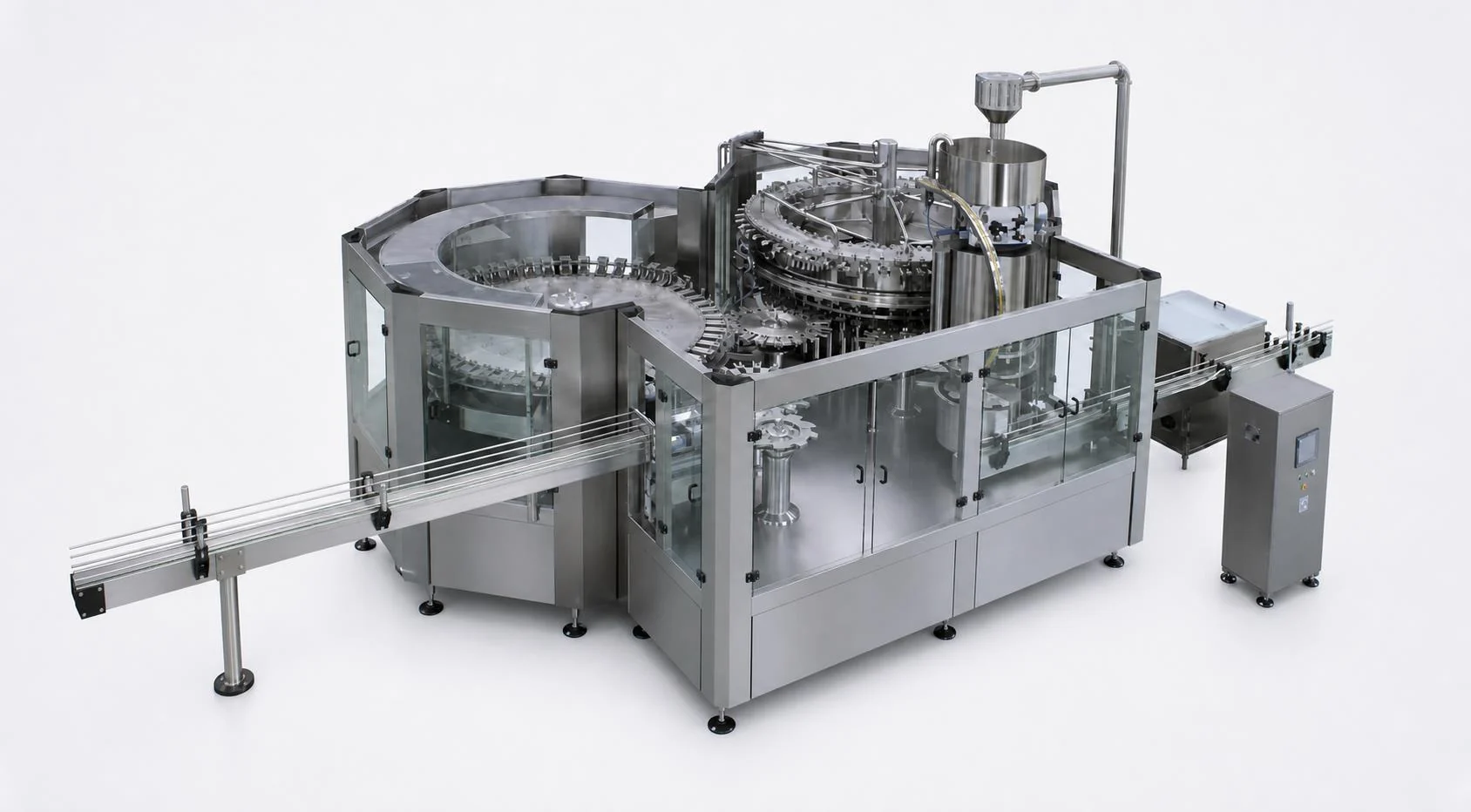
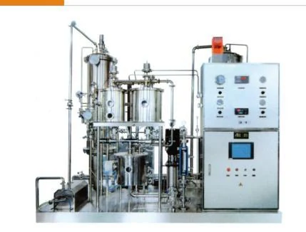

Answer first
Usable mixer output, inlet product conditions, CO2 supply and quality, carbonation target, storage pressure and temperature must be confirmed with the filler operating basis.
Product + CO2
Prepared water/product, syrup where applicable and filtered CO2 enter the system. Exact ratios and gas content are recipe decisions.
Temperature basis
The catalog reference identifies chilled inlet conditions for its mixer platforms. Do not copy a generic temperature into a project; confirm it with product, mixer and filler selection.
CIP + pressure
The route needs cleanable product contact surfaces, compatible pumps/tanks and pressure control through delivery to the filler.
Carbonation interface matrix
Temperature, dissolved gas, pressure, flow and transfer behavior are connected observations; the table does not prescribe universal setpoints.
| Changed condition | What to observe | Likely interface affected | Confirmation needed |
|---|---|---|---|
| Prepared-product variation | Recipe ratio, incoming flow and batch or continuous consistency | Mixer or carbonator inlet and final beverage consistency | Approved recipe basis and stable inlet condition |
| Higher or unstable temperature | Product inlet, chiller outlet, transfer path and site heat gain | CO2 dissolution, delivery stability and filler behavior | Project-specific temperature basis and available cooling duty |
| Different CO2 target | Gas supply, quality, dosing or mixing basis and dissolved-gas result | Carbonator duty, pressure boundary and package review | Confirmed target and measurement responsibility |
| Variable product flow | Upstream delivery, buffer level, pump behavior and filler demand | Carbonation consistency and filler starvation or cycling | Common sustained-flow and buffer-control basis |
| Transfer pressure loss | Pipe route, restrictions, elevation, valves, buffer and filler inlet | Gas breakout risk and pressure-controlled handover | Agreed delivery-pressure window for the project |
| Frequent downstream stops | Filler state, return or hold behavior, product temperature and buffer response | Recirculation, carbonation stability and restart sequence | Defined stop, hold, return and restart logic |
| Package change | Container and closure pressure basis plus filler and downstream interfaces | Filling, closure, inspection and product handling | Reconfirmed complete package architecture |
Carbonation-system boundary
The carbonation section connects a prepared beverage to a pressure-controlled filling condition; it does not own the entire CSD line.
Start with a known beverage stream and declared recipe, flow and temperature condition.
Coordinate CO2 supply, gas incorporation, pressure control and transfer through the selected route.
Declare the product condition and operating states at the pressure-controlled filler inlet.
Carbonation brief
A CO2 target by itself cannot describe the product-delivery architecture.
Illustrative interface diagnosis
A carbonated line shows less stable filling after the product pipe route is revised, while the recipe and nominal filler settings appear unchanged.
Preliminary resultThe investigation treats chilling, carbonation, transfer and filling as one connected interface without assuming a universal cause or remedy.
Illustrative only. No pressure, temperature, gas target or troubleshooting outcome is guaranteed.
Evidence boundary
Evidence labels keep a reference architecture separate from a final design or commercial promise.
The supplied 2026 catalog connects water chilling, drink mixing, syrup preparation, CO2 supply, CIP and pressure-controlled filling in its CSD reference route.
Stable carbonation and isobaric filling depend on the connected product temperature, dissolved gas, flow, pressure and transfer conditions.
Final targets, equipment, pipework, controls, operating states, package compatibility, output and acceptance require confirmed project data.
Buyer questions
These are planning answers. Final process and equipment choices require a confirmed project brief.
No. Product temperature, carbonation, flow, transfer losses, package condition and filler operation must be reviewed together before a cause or adjustment is assigned.
No. Recipe flow, inlet condition, cooling duty, CO2 supply, buffer and transfer route, filler demand, operating states and site conditions also require confirmation.
Product temperature, dissolved CO2, pressure and transfer conditions form one confirmed basis for stable pressure-controlled filling.
No. Recipe, product flow, inlet condition, site conditions, storage/delivery and filler basis must be confirmed together.
Catalog reference The supplied 2026 catalog supports the named CSD and juice/tea equipment chains and is the source for the redrawn functional routes.
Engineering principle Interface explanations show why product, process, package, utilities and line balance must be reviewed together.
Project confirmation The routes are not a final process design, P&ID, validated cycle, quotation, availability statement or performance guarantee. Signed project documents define the final scope.
Allot Tech project desk
For a useful first reply, send the beverage, package, target good output and factory. If a line is already operating, add the observed symptom, first-known-good and first-known-bad time, affected SKU, photos, alarms and available production data.
Company verification: visit allottech.com.